HSUPA
Vol. I, HSUPA

The technical history of mobile uplink.

An editorial reference on HSUPA, 3G hardware ecosystems, and the uplink architecture that shaped modern cellular networks. Three practitioner pieces on the standards, equipment, and design decisions that carried mobile broadband from 3.5G to 5G NR.

Cell tower infrastructure representing HSUPA 3G mobile broadband
No.01ARCHITECTUREApril 28, 2026

From HSUPA to 5G: The Evolution of Mobile Uplink Technology

A technical walkthrough of how mobile uplink architecture evolved from HSUPA's 3.5G packet access through LTE to modern 5G NR, and what that progression means for practitioners today.

Signal tower infrastructure representing 3G to 5G uplink evolution

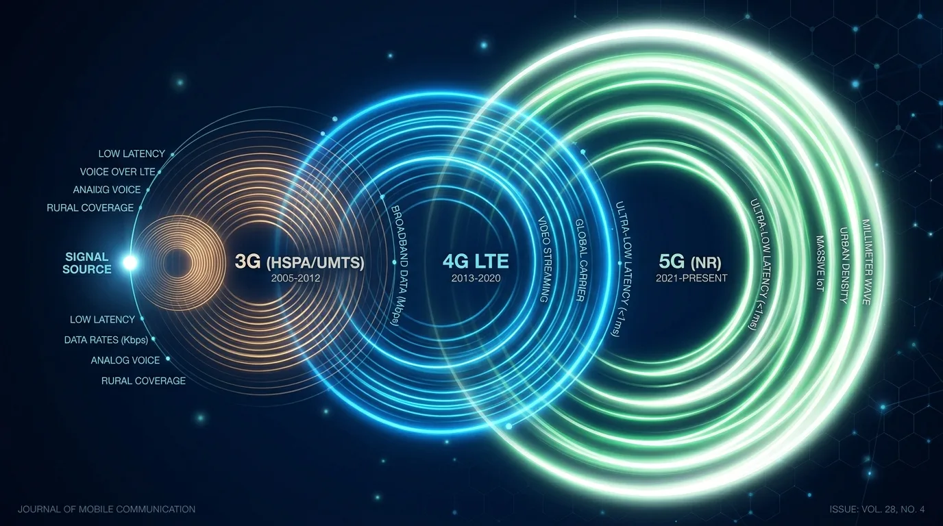
Mobile uplink performance has always lagged download throughput in cellular network design. When High-Speed Uplink Packet Access (HSUPA) arrived as 3GPP Release 6 in 2004, it addressed exactly this asymmetry in WCDMA networks. More than two decades later, the same fundamental problem drives 5G NR uplink enhancements, the mechanisms just operate at a different scale.

This article traces the architectural thread from HSUPA through LTE to 5G NR, with emphasis on how each generation solved the uplink bottleneck and what practitioners running mobile infrastructure or IoT deployments should understand about that lineage.

What HSUPA Actually Solved

Before HSUPA, WCDMA uplink used the Dedicated Channel (DCH) with relatively slow rate control. The Node B had limited visibility into per-UE buffer status, and scheduling decisions were made primarily by the RNC, introducing latency and inefficiency.

HSUPA, formally called Enhanced Dedicated Channel (E-DCH), moved scheduling intelligence down to the Node B. The key mechanisms were:

  • E-DPCCH and E-DPDCH: Separate control and data channels on the uplink, allowing the UE to signal its buffer status and power headroom in real time.
  • Node B-controlled scheduling: The base station could grant transmission resources within 2 ms or 10 ms TTIs, dramatically improving reaction time to changing radio conditions.
  • Hybrid ARQ (HARQ) with soft combining: Retransmitted packets were combined with earlier attempts at the receiver, improving effective throughput without consuming additional spectrum.
  • Multi-code transmission: Peak rates of 5.76 Mbps were achievable on devices supporting the highest category, versus the 384 kbps typical on DCH.

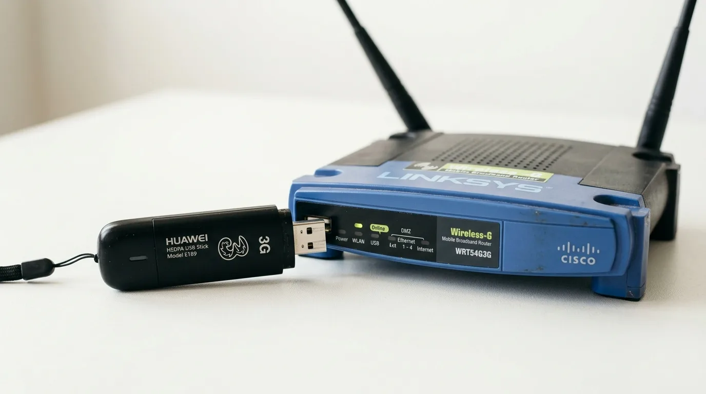
For devices like the Toshiba Portégé G810 and Sony Ericsson XPERIA X1, flagship hardware at the time hsupa.com covered them, these gains meant practical uplink speeds that made mobile multimedia sharing viable for the first time.

The HSPA+ Bridge

3GPP Release 7 extended HSPA with MIMO support and higher-order modulation (64QAM on downlink, 16QAM on uplink), marketed broadly as HSPA+. Release 8 added dual-carrier operation.

From an uplink perspective, the most significant Release 7 addition was 16QAM on E-DPDCH, lifting the theoretical uplink peak to 11.5 Mbps on Category 7/8 devices. More practically, continuous packet connectivity (CPC) introduced a discontinuous transmission mode that reduced interference and extended battery life, a direct enabler of always-on mobile data behavior that users now consider standard.

The HSPA+ era also saw carriers like AT&T and Vodafone deploy software upgrades to existing HSUPA base stations rather than full hardware replacement, demonstrating the architectural flexibility that 3GPP had designed into the E-DCH framework.

LTE: Rewriting the Uplink Stack

LTE (3GPP Release 8) replaced WCDMA entirely with OFDMA on the downlink and SC-FDMA on the uplink. The SC-FDMA choice was deliberate: it retains the low peak-to-average power ratio (PAPR) advantage of single-carrier waveforms, reducing UE power amplifier demands compared to straight OFDMA.

LTE uplink scheduling operates on a 1 ms subframe (TTI), eight times shorter than HSUPA's 8 ms practical scheduling interval in many deployments. The eNodeB handles all uplink scheduling decisions, a complete collapse of the split RNC/Node B model from HSUPA.

Key LTE uplink advances over HSUPA:

FeatureHSUPA (Release 6)LTE Release 8
Peak uplink (theoretical)5.76 Mbps75 Mbps (2x2 MIMO)
Scheduling TTI2 ms / 10 ms1 ms
WaveformWCDMA (spread spectrum)SC-FDMA
HARQ processesUp to 8Up to 8
Scheduler locationNode BeNodeB (no RNC split)

LTE-Advanced (Release 10) added uplink carrier aggregation, allowing UEs to transmit on multiple component carriers simultaneously and pushing theoretical uplink peaks above 1 Gbps in lab conditions.

5G NR Uplink: Where the Architecture Stands Today

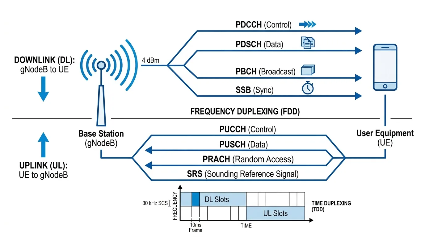
5G NR (New Radio, Release 15 and beyond) introduces flexible numerology through its subcarrier spacing options (15 kHz to 240 kHz), allowing the same spectrum to be configured for different latency and throughput targets. For uplink specifically, NR brings several advances that practitioners deploying private networks or cellular IoT should understand.

Uplink Waveform Flexibility

NR supports both CP-OFDMA and DFT-s-OFDM (the SC-FDMA successor) on the uplink. The choice is per-slot and per-UE. DFT-s-OFDM remains preferred for coverage-limited scenarios, edge devices and IoT endpoints, because of its PAPR advantage, while CP-OFDMA enables higher spectral efficiency when link budget is not the constraint.

Enhanced HARQ and Mini-Slots

NR introduces mini-slot scheduling (2 or 7 symbols versus a full 14-symbol slot), enabling sub-millisecond uplink transmissions. This directly benefits latency-sensitive applications, industrial automation, vehicle-to-infrastructure messaging, and remote monitoring, that were impossible on HSUPA's 10 ms TTI and impractical even on LTE's 1 ms TTI due to scheduling overhead.

Uplink Power Control Refinements

NR uplink power control inherits LTE's fractional path-loss compensation model but adds enhancements for massive MIMO scenarios. With base stations deploying 64 or more antenna elements, spatial multiplexing allows multiple UEs to transmit on the same time-frequency resource. The system manages inter-user interference through beamforming rather than orthogonal resource allocation alone.

5G Uplink in Private Networks

Private 5G NR deployments in manufacturing, logistics, and utilities frequently prioritize uplink performance in ways public networks do not. A camera-equipped autonomous robot uploading real-time video for edge inference has stricter uplink requirements than a smartphone user streaming Netflix. Network slicing and QoS frameworks in NR allow operators to carve dedicated uplink capacity for these use cases, a capability that HSUPA's single-bearer model could not approach.

Practical Implications for Network Planners

The throughput numbers across generations are well-known. Less discussed are the planning implications:

Coverage vs. capacity trade-offs persist. HSUPA's uplink improvement was partly a coverage improvement, HARQ soft combining and power control adjustments meant edge UEs could maintain usable uplink rates where DCH would have failed. NR DFT-s-OFDM serves the same purpose in 5G. When planning 5G deployments, uplink coverage budgets require separate modeling from downlink.

Backhaul and fronthaul have shifted. HSUPA's Node B scheduling required synchronization but kept baseband processing at the RNC. Modern 5G Centralized RAN (C-RAN) or Open RAN architectures pull baseband to a central unit, placing strict latency requirements on fronthaul. Network planners transitioning from 3G infrastructure need to account for this architectural inversion.

IoT uplink dominates new use cases. NB-IoT and LTE-M remain widely deployed for low-power applications. 5G RedCap (Reduced Capability, Release 17) targets mid-tier IoT devices that need more than NB-IoT can offer but do not justify full NR complexity. Understanding uplink behavior in these reduced-capability modes is increasingly central to IoT platform selection.

Conclusion

HSUPA established that uplink scheduling, HARQ, and close coupling between the UE and base station are the right architectural primitives for high-performance mobile uplink. Each subsequent generation, HSPA+, LTE, LTE-Advanced, and 5G NR, has refined those same primitives rather than discarding them. Practitioners who understand why HSUPA worked the way it did will find the 5G NR uplink design considerably more legible than those approaching it cold.

Related reading on hsupa.com:


No.02HARDWAREApril 15, 2026

Guide to 3G Mobile Broadband Hardware: Routers, Data Cards, and What They Got Right

A practitioner's reference on the HSUPA-era hardware ecosystem, USB dongles, ExpressCard modems, and mobile routers, and how those design decisions informed modern cellular modem architecture.

Vintage 3G USB modem and mobile broadband hardware

The period from roughly 2007 to 2012 produced a specific category of hardware: devices built explicitly to expose HSUPA's uplink capability to end users and enterprises. USB modems, ExpressCard data cards, embedded mobile routers, and HSUPA-capable smartphones all shared the same fundamental requirement, translating the physical layer gains of E-DCH into usable connectivity for applications.

Understanding how that hardware was designed, what constraints it operated under, and where it succeeded and failed provides useful context for evaluating modern cellular IoT modules, industrial routers, and embedded 5G solutions that descend from the same lineage.

The Form Factor Landscape

USB Modems (Dongles)

The USB modem was the dominant consumer form factor for HSUPA access. Devices from Huawei, Sierra Wireless, ZTE, and Option N.V. plugged directly into a laptop's USB port and presented a virtual serial interface or NDIS interface to the host operating system.

Key specifications that differentiated HSUPA dongles from earlier HSDPA-only models:

  • HSUPA category support: Cat 5 devices supported 2 Mbps uplink; Cat 6 reached 5.76 Mbps. Many early "HSPA" dongles supported only HSDPA downlink with W-CDMA uplink, a distinction retailers rarely highlighted.
  • Antenna design: Internal helical or PIFA antennas were adequate for urban coverage but limited in fringe areas. Some enterprise-grade dongles added external antenna connectors, a feature that reappeared as a standard requirement in modern LTE and 5G modules.
  • Driver architecture: Windows-first driver stacks were the norm. Linux support ranged from community-maintained to nonexistent, a friction point that pushed enterprises toward hardware with more portable AT command interfaces.

The Sierra Wireless AirCard 875U and Huawei E220 were representative of the category. Both shipped with carrier-branded software that provided signal monitoring and connection management, the direct predecessor to modern modem management APIs.

ExpressCard and PC Card Modems

Enterprise laptops of the era often included ExpressCard/34 or PC Card slots, and cellular modem manufacturers targeted these for better thermal performance and persistent connectivity. ExpressCard modems avoided the USB enumeration overhead and generally presented more stable interfaces for enterprise VPN and always-on applications.

The Sierra Wireless AirCard 880E and Novatel Wireless EU870D were common in this category. Both supported external antenna connection, and several carriers offered them as primary broadband solutions for locations with marginal 3G coverage where the gain from an external antenna made the difference between a usable connection and none.

Mobile Routers and MiFi Devices

The MiFi concept, a battery-powered device that terminates the cellular connection and presents a local Wi-Fi access point, emerged during the HSUPA era and addressed a fundamental limitation of USB dongles: they served one host at a time.

Novatel Wireless's MiFi 2200 (2009) became the reference design for this category. It combined an HSPA modem, a Wi-Fi 802.11b/g access point, and a battery into a credit-card-sized device. From a network perspective, the MiFi introduced NAT between the cellular bearer and connected devices, which had practical implications for applications requiring end-to-end addressing, a problem that cellular IoT architects still navigate today when distinguishing between devices behind carrier-grade NAT and those with direct IP assignment.

Integrated Devices: HSUPA Smartphones and Laptops

Smartphones incorporating HSUPA modems represented a different integration model, the radio as a system component rather than an accessory. The Sony Ericsson XPERIA X1 and Toshiba Portégé G810 (the latter embedding HSUPA alongside a full laptop platform) demonstrated that integrating uplink-capable 3G into primary computing devices was feasible at the power and thermal budgets available.

The Portégé G810 in particular illustrated the enterprise mobile broadband use case: a professional device where cellular connectivity was persistent rather than supplemental, relevant to field service, public safety, and mobile workforce deployments. That positioning maps directly to modern enterprise laptops with embedded LTE/5G and always-on connectivity management.

Modem Chipsets and AT Command Interfaces

Behind all of these form factors sat a small number of modem chipset families. Qualcomm's MDM series, Ericsson Mobile Platforms (later acquired and folded into ST-Ericsson and eventually Intel), and Option's GlobeSurfer chipsets powered most of the market.

The AT command interface, originally standardized for dial-up modems and extended through Hayes-compatible expansions, remained the primary control plane for HSUPA modems. Carrier-specific extensions handled:

  • Network selection and band locking
  • Signal quality reporting (RSSI, RSCP, Ec/No for WCDMA)
  • USSD and SMS passthrough
  • Data call establishment via +CGDCONT and ATD99**1#

These same AT commands, with additions for LTE (3GPP TS 27.007 and TS 27.005), remain the standard interface for cellular modules in IoT deployments today. Engineers working with Quectel, u-blox, or Sierra Wireless modules on LTE-M or 5G RedCap projects are using a control interface whose core grammar was set during the HSUPA era.

Antenna Design Constraints

HSUPA operated in licensed spectrum bands, typically 850 MHz, 900 MHz, 1900 MHz, and 2100 MHz depending on carrier and region. Antenna design for USB dongle form factors required fitting resonant structures for multiple bands into enclosures with minimal ground plane.

The dominant approaches:

PIFA (Planar Inverted-F Antenna): Low profile, ground-plane dependent, suitable for integration into flat enclosures. Most USB dongles used PIFA variants tuned for primary operating bands.

Helical antennas: Volumetrically efficient, less ground-plane dependent, used in earlier and smaller form factors. Bandwidth was narrower, which became a constraint as devices needed to cover more bands.

External connector options: SMA or TS-9 connectors allowed connection to external directional or high-gain antennas. This feature was critical for fixed wireless installations where the modem served as a CPE substitute. The same design consideration applies directly to modern industrial cellular routers where external antenna support is often a procurement requirement.

Power Management and Thermal Considerations

HSUPA transmission at peak rates (5.76 Mbps) drove significant power consumption in UE devices. Maximum UE transmit power in WCDMA is 24 dBm (power class 3, the most common for data devices), and sustained uplink transmission approached this limit under poor coverage conditions.

USB dongle thermal performance was often constrained by the USB enclosure's surface area and the host system's USB power delivery (500 mA at 5V = 2.5W maximum from a standard port). In practice, modems regulated transmission power and rate based on available power budget, meaning a modem running from a low-power USB hub performed differently than one connected to a direct host port.

This power-thermal interaction has a direct parallel in modern 5G NR modules. Sub-6 GHz modules in USB or M.2 form factors face similar constraints, and mmWave modules in particular require careful thermal design because their power amplifier efficiency at 28 GHz or 39 GHz is significantly lower than at 2.1 GHz.

What This Hardware Got Right

Several design decisions from the HSUPA hardware era have proven durable:

Separating the cellular connection from the application host. The MiFi model, modem as a network edge device rather than a host peripheral, aligns with how industrial IoT deployments are increasingly architected. Cellular routers with local processing capability (edge compute + connectivity) are a direct evolution.

External antenna connectivity. Devices that shipped with antenna connectors consistently delivered better performance in enterprise and fixed deployments. Modern M.2 cellular modules almost universally include antenna connectors as a result.

AT command standardization. The decision to standardize on extensible AT command interfaces rather than proprietary binary protocols meant that software stacks developed for HSUPA modems could be adapted for HSPA+, LTE, and now 5G with incremental changes rather than full rewrites.

Band and operator flexibility. Unlocked HSUPA devices that supported multiple frequency bands set the expectation for multi-band cellular hardware that now defines industrial IoT module specifications.

Conclusion

The 3G mobile broadband hardware ecosystem was not just a historical footnote, it established form factors, interface standards, and design trade-offs that define the cellular hardware landscape today. Engineers selecting cellular modules for IoT platforms, industrial routers for private network deployments, or embedded connectivity solutions for mobile computing will find that many of the questions they are asking, antenna design, power budget, AT command interface, NAT behavior, were first worked through on HSUPA-era hardware.

Related reading on hsupa.com:


No.03STANDARDSMarch 22, 2026

HSUPA vs HSDPA: Understanding 3.5G Architecture and Its Modern Relevance

A technical comparison of HSUPA (uplink) and HSDPA (downlink) within the HSPA framework, covering channel design, scheduling, HARQ, and how these mechanisms influenced LTE and 5G NR architecture.

Abstract network architecture diagram for 3.5G HSPA standards

HSDPA and HSUPA are frequently mentioned together under the HSPA umbrella, but they address different problems, use different channel structures, and were standardized in separate 3GPP releases. Understanding the distinction matters for anyone working with legacy UMTS networks, reading 3G performance data, or trying to understand why LTE and 5G NR made the architectural choices they did.

This article compares HSDPA and HSUPA at the channel, scheduling, and HARQ levels, then maps those design decisions to their equivalents in contemporary cellular systems.

Background: The WCDMA Baseline

Before either HSDPA or HSUPA, WCDMA (Wideband CDMA, Release 99) provided uplink and downlink data services through Dedicated Channels (DCH). Both directions used the same basic mechanism: RNC-controlled rate setting, soft handover on both uplink and downlink, and relatively slow adaptation to changing radio conditions.

The limitation was structural. The RNC sat above the Node B in the network hierarchy. Rate changes required signaling that traversed the Iub interface between Node B and RNC, introducing delays of 100 ms or more. In a radio environment where channel quality can change significantly within 10 ms, this reaction time severely limited throughput efficiency.

HSDPA (Release 5, 2002) addressed the downlink first. HSUPA (Release 6, 2004) followed for the uplink. Together they formed HSPA, High-Speed Packet Access, the system that would brand 3.5G networks commercially.

HSDPA: The Downlink Solution

HSDPA introduced the High-Speed Downlink Shared Channel (HS-DSCH). Key characteristics:

Shared channel, fast scheduling. HS-DSCH is time-shared among UEs in a cell on a 2 ms TTI basis. The Node B scheduler selects which UE to serve in each TTI based on channel quality reports (CQI) sent by UEs every 2 ms. This is proportional fair or maximum C/I scheduling, depending on implementation.

Adaptive modulation and coding (AMC). Rather than adjusting transmit power to compensate for channel variation (as DCH did), HSDPA adjusts modulation and coding rate. Good channel conditions: 16QAM with high-rate turbo code. Poor conditions: QPSK with low-rate code. The transmit power stays roughly constant; the information rate adapts.

HARQ at the Node B. Retransmissions are handled at the Node B rather than at the RNC. The UE sends ACK/NACK within one TTI, and the Node B retransmits immediately. Chase combining or incremental redundancy is used to combine retransmissions with previous attempts.

No soft handover. HS-DSCH does not support soft handover, which was a feature of DCH. Serving cell handover for HSDPA is handled by a hard handover mechanism (HS-DSCH serving cell change). This was initially considered a downgrade, but the gains from fast scheduling and AMC more than compensated.

HSDPA peak rates progressed through device categories:

HSDPA CategoryModulationCodesPeak Rate
Cat 1-2QPSK51.2 Mbps
Cat 3-4QPSK51.8 Mbps
Cat 5-6QPSK / 16QAM53.6 Mbps
Cat 7-816QAM107.2 Mbps
Cat 1016QAM1514.4 Mbps

HSUPA: The Uplink Solution

HSUPA, formally Enhanced Dedicated Channel (E-DCH), took a different approach than HSDPA because the uplink has fundamentally different constraints:

  • Multiple UEs transmit simultaneously on shared spectrum, creating mutual interference.
  • UE power is limited (typically 24 dBm maximum), unlike a base station.
  • The UE, not the network, controls when and how much it transmits.

The E-DCH design addressed these constraints through Node B-controlled scheduling with UE feedback rather than network-unilateral scheduling as in HSDPA.

E-DCH Channel Structure

HSUPA introduced several new uplink channels:

E-DPDCH (Enhanced Dedicated Physical Data Channel): Carries user data. Up to four parallel E-DPDCHs can be configured for higher data rates (multi-code transmission).

E-DPCCH (Enhanced Dedicated Physical Control Channel): Carries control information from the UE: E-TFCI (transport format combination indicator, describing what the UE is transmitting), RSN (retransmission sequence number for HARQ), and Happy Bit.

E-AGCH (E-DCH Absolute Grant Channel): Downlink channel from Node B granting the UE an absolute maximum transmit power ratio. Used for initial grant and reconfiguration.

E-RGCH (E-DCH Relative Grant Channel): Downlink channel for incremental up/down commands. Allows the Node B to quickly adjust UE transmit power in steps without the overhead of a full absolute grant.

E-HICH (E-DCH HARQ Indicator Channel): Carries ACK/NACK for HSUPA retransmission control.

The Happy Bit

One of the more operationally interesting aspects of HSUPA is the Happy Bit, a single bit in the E-DPCCH that signals whether the UE is satisfied with its current grant. If the UE has more data buffered than its current grant allows it to transmit, it signals "unhappy" (0), prompting the Node B scheduler to consider increasing its grant. If the UE has no additional backlogged data, it signals "happy" (1).

This feedback mechanism allows the scheduler to prioritize UEs with pending data without requiring full buffer status reports in every TTI, an efficient encoding of scheduling-relevant information in a single bit. Later systems used more detailed Buffer Status Reports (BSR) in LTE and NR, trading simplicity for precision.

TTI Options and Scheduling

HSUPA supported two TTI lengths: 2 ms and 10 ms. The 2 ms TTI provided lower latency and faster HARQ feedback but required higher UE processing capability. The 10 ms TTI was specified first (Release 6) and was supported by a broader range of devices.

Most HSUPA deployments used 10 ms TTI initially. Carriers deploying HSUPA in conjunction with HSDPA in the same carriers found that 10 ms HSUPA was often sufficient to match realistic application uplink demands of the era.

Direct Comparison

DimensionHSDPAHSUPA
3GPP ReleaseRelease 5 (2002)Release 6 (2004)
DirectionDownlinkUplink
Channel nameHS-DSCHE-DCH
Scheduling entityNode BNode B (with UE feedback)
TTI2 ms2 ms or 10 ms
AMCYes (QPSK to 16QAM)No (power variation + code rate)
HARQChase combining / IR at Node BChase combining / IR at Node B
Soft handoverNo (hard serving cell change)Soft handover retained
Peak rate (Release 6)14.4 Mbps5.76 Mbps

The asymmetry in peak rates reflects the fundamental difference between a base station transmitter (high power, multiple antennas, no size constraint) and a UE transmitter (power-limited, thermally constrained, form-factor limited). This asymmetry persists through LTE and into 5G, where downlink peak rates typically exceed uplink by a factor of 2-4x in standard configurations.

The retention of soft handover on HSUPA uplink was a notable difference from HSDPA. Because multiple cells receive the same uplink signal from a UE in soft handover, the signals can be combined at the RNC (macro diversity combining). This improves uplink coverage at cell edges, relevant for devices transmitting at power limits in poor coverage conditions.

Influence on LTE Design

LTE's architects borrowed from both HSDPA and HSUPA but simplified the structure considerably:

From HSDPA: The shared downlink channel model, Node B scheduling, AMC, and HARQ at the base station all carried forward to LTE. The PDSCH (Physical Downlink Shared Channel) is conceptually the HSDPA model matured.

From HSUPA: The Node B-controlled uplink scheduling model, HARQ on the uplink, and the principle of fast UE feedback carried forward to LTE's PUSCH (Physical Uplink Shared Channel). LTE eliminated the Happy Bit in favor of full Buffer Status Reports, and dropped soft handover entirely (LTE uses hard handover only), but the core scheduling loop originated with HSUPA.

What LTE discarded: The split RNC/Node B architecture was collapsed entirely. LTE's eNodeB handles all scheduling, HARQ, and handover decisions internally (with X2 interface coordination for handovers). This architectural change would have been much harder to make without the experience of deploying HSDPA and HSUPA, both of which demonstrated that moving intelligence to the base station worked.

Relevance for Modern Networks

HSPA networks remain operational in many markets as 4G and 5G coverage continues to expand. Some specific contexts where HSUPA/HSDPA behavior remains practically relevant:

IoT fallback scenarios. NB-IoT and LTE-M devices are designed to fall back to GPRS in areas without LTE coverage. In regions where HSPA is the highest available technology, IoT devices may operate on HSPA rather than LTE. Understanding HSUPA E-DCH behavior is relevant to troubleshooting uplink performance in these scenarios.

Legacy MVNO infrastructure. Several MVNOs continue to offer HSPA-only plans on roaming agreements. Devices operating on these plans see HSUPA uplink performance, and diagnostic tools that report E-DCH category information can help distinguish between HSPA device category limitations and coverage limitations.

3G sunset planning. Network operators decommissioning 3G infrastructure need to understand which traffic types depended on HSUPA characteristics, specifically, applications that relied on sustained uplink performance at sub-5 Mbps rates. Migrating these to LTE requires ensuring adequate uplink coverage in the areas previously served by HSPA.

Conclusion

HSDPA and HSUPA solved complementary problems using compatible mechanisms, both moved scheduling to the Node B, both implemented HARQ at the air interface level, and both used short TTIs to enable fast adaptation. Their differences, HSDPA's downlink shared channel versus HSUPA's uplink scheduled grant model, HSDPA's AMC versus HSUPA's power and code adaptation, reflect the distinct physical constraints of the two link directions.

Those architectural decisions were not discarded when LTE arrived; they were simplified, unified, and scaled. Understanding the original HSPA design makes the LTE and 5G NR air interface considerably more legible.

Related reading on hsupa.com: